zaterdag 7 juli 2012
Traffic Lights - Part I


I started by cutting the face plate for each traffic light from thin styrene sheet, then carefully drilled 3 � 2mm holes in each face plate, spacing each hole 1/8� apart (center to center). For the lens shades, I used a single hole punch to punch out round pieces from very thin styrene. I cut the styrene disk back 2mm from its edge, trimmed each pointy edge, and shaped each piece by gently rolling it between my fingers until it had the correct curve to fit over each LED. I was able to make 2 shades from each styrene disk. I then glued 3 of these directly above each hole on the face plate.


I masked the backside of each face plate, and sprayed the front flat back, figuring that it would probably be easier to paint these prior to installing the lights. I masked the back side to prevent paint from getting on this area, which would need to be removed anyways when it came to gluing the LEDs to the face plate. I then counted out 6 LEDs in each colour (red, yellow, green) and tested each one with a resistor and power supply to ensure each one worked.


For the light standards, I used 3/32� diameter copper tubing, which I cut into 4� sections. I cut the sections at 4� so I had extra length to insert into the pilot holes in my layout when it comes to installing these. I needed to thread 4 wire leads through each, so the wires needed to be quite thin. I found an old computer hard drive ATA cable, which is comprised of several dozen very thin insulated wires, so I cut this up and saved the wire leads. I then threaded 4 wires through each copper tube, one for the green, yellow, red LEDs, and common ground. There were only 3 colours of wire however (red, blue, and white), so I just used a second white, marking it with a black sharpie for use as the common connection.


Once the wire leads were threaded through each copper tube, I bent the top of each tube to an almost 90 degree angle about 1� from the one end. I bent the curve over a thick marker container to keep the curve uniform and round. It�s also very important to make sure that the wire leads are pre-installed in the copper tubes, as the tube needs the internal support when bending. Without the wire leads inside, the copper tube would simply collapse and kink.


By this time, the paint on the front of the face plates had dried, and it was time to install the LEDs. I first cut off the long connectors to each LED with flush cutters, leaving only a small portion protruding from the back of each LED. I then glued each LED with CA to the back of the face plates, making sure the anode (+) connection on each LED was on the top position. You can distinguish what side is the anode connection on most LEDs from the curved profile on the base of the LED itself. The cathode (-) side is flat and squared off, and the actual connection lead itself is usually shorter than the anode.

Now for the fun part; soldering the connections to the LEDs. I used a small cardboard box which I cut a notch into for the front of the faceplate to fit into for support. The common (-) connection was the first one that I made. For this, I used one of the metal leads that I had originally cut off of the LEDs, spanning it across and soldering it to all three cathode connections on the LEDs.


For the controlled (+) connections, I carefully soldered each wire lead from the copper tube supports to the anode on each LED. I soldered the red wire to the red LED, the blank white wire to the yellow, and the blue one to the greed LED for each traffic light. The other white wire, which I previously marked with a black sharpie, was soldered to one end of the common connection. When soldering the wires, I made a point of positioning each wire so it would easily exit off to one side of the traffic light (the side facing the support column). This made the back of each street light look a lot less cluttered and easy to work with.


Once all connections were made, I gently and carefully (and I stress the gentle part), pulled the wire leads at the base of the copper tube supports, slowly bringing each traffic light closer to the support column. After I had positioned each traffic light right up against the copper tube supports, I adjusted each light so it was positioned level to the ground when positioned upright. The wires provided enough rigidity that no glue was required to fasten the lights to the support column. I then painted the back side of each light, including the connections and face plate, with 3-5 coats of black enamel paint, making sure I put on enough coats that no light was visible from the back of the traffic lights when lit.


The final step was to paint the copper support columns an aluminum colour, for which I used Humbrol metallic aluminum enamel. With the traffic lights now complete, they only now need to be installed and connected to a traffic light controller on my layout. I am currently exploring a couple of options for controllers, including building my own. That will all however be in my Traffic Lights � Part II post, which will hopefully be up sometime this summer. For now, I will return back to my current task of building more trees.
donderdag 28 juni 2012
Walthers Northern Light & Power Kit


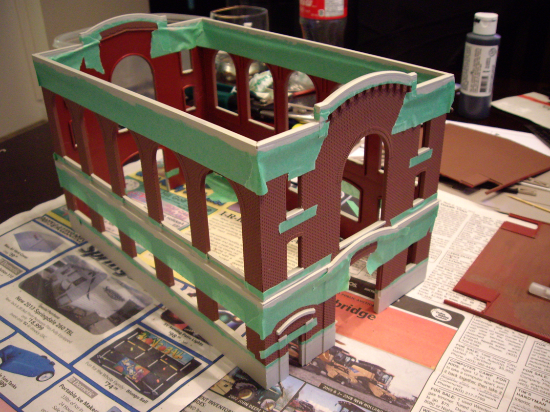
Like all Walthers Cornerstone kits, all pieces are precision molded with quality materials. Besides the 4 walls, roof, one-piece chimney, and base pieces, the kit includes an under-track hopper kit, roof support trusses, an internal firewall, roof vents, and the separate windows and doors. The separate windows and doors are my personal favorite, as they make painting much easier and convenient as there is much less masking required. Before I started painting and assembling, I carefully cut each piece off of its plastic carrier structure and trimmed/sanded off any spurs, and washed each piece in warm, soapy water.

I started by carefully assembling the 4 main walls, ensuring the structure was kept level and the walls joined at a perfect 90 degrees. I then painted the main structure with brick red Humbrol enamel, thinned 3:1 with thinner. I also used the same paint colour on the chimney and firewall pieces. At the same time, I also sprayed the windows and doors with Testors light aircraft gray. I didn�t remove the windows at this point from their carrier, making them much easier to paint in one easy step. Other small components, such as the roof vents and trusses, were painted with metallic aluminum paint.


After the main structure dried for 24 hours, I masked the entire building to prepare for painting the trim and foundation. I used the same light aircraft grey colour that I used on the windows for the trim, which took about 3 coats as I was brush-painting them. Once the trim had completely dried, I made any necessary touchups with either the brick red or light aircraft grey paint using a fine detailing brush. I then weathered the entire building with powdered pastels and sealed it with 2 coats of Testors Dull-Coat.

I felt that the roof pieces lacked any detail, so I used trip styrene to add a bit of this lacking detail. I first divided each roof panel into 4 equal sections by gluing 1mm x 1.5mm strip styrene directly onto the roof. I then glued a piece of the strip styrene along the total length of the edge of one roof section. I made sure this piece overhung the roof panel slightly, thus covering the gap between the 2 roof sections once they were assembled on the structure. The entire roof was then spray painted flat black.


For the large double door, side entry door, and overhead bay door, I used dark green enamel to add a bit more interest to the colour scheme of the building. I masked off the door frames and transoms so they would remain the light grey colour I had originally coloured them. The last step was to weather the doors with dark powdered pastels and seal with a final coat of dull-coat. The windows were also weathered and sealed with the same method.


The clear styrene window glazing included with the kit is less than satisfactory. The glazing is thick and oddly obscured, so I opt to use clear styrene from Evergreen, which is thin and almost perfectly clear, looking much more like real glass. After removing each window from its carrier, I carefully glued it to a clean sheet of the clear Evergreen styrene. I glued each window side by side to get as much use out of the styrene sheet as possible, leaving only a large enough gap between each window to accommodate a razor-blade. After the glue had dried, I carefully cut each window with a sharp hobby blade, and trimmed off any overhanging styrene where needed. This process went much quicker than anticipated, and before I knew it, I had a nice pile of glazed windows ready for installation.

Before installing the windows, I first painted the interior walls with dark grey enamel. I also scraped the paint off of the surfaces of the windows and window openings where glue would be applied for a stronger bond. I then applied a small bead of glue around each window, and mounted it to the inside of each opening, pressing down for several seconds to ensure it was properly seated. Once the windows were all installed, I added the 3 roof support trusses and the firewall section.


Lighting was next. I didn�t use the styrene light diffuser box I had used in previous models, mainly due to the fact that this building�s interior is completely open and visible due to the large amount of windows. I instead wired 2 automotive 12v bulbs between the roof support trusses, using rigid steel wire to support each bulb. I originally wired the bulbs in series, but they were too dim at 12 volts, so I adjusted the wiring to a parallel circuit, allowing the bulbs to glow much brighter at the same voltage. The wire leads run down the back wall and exit out of 2 small holes in the structure�s foundation.


The interior was by far the most challenging task of the whole project. I knew the staple piece of equipment for any press company is the printing press itself, so I immediately went to work scratch building a large press from scrap styrene. Once the press started to look somewhat realistic, I sprayed it flat black, and detailed it with metallic aluminum rollers and highlights. The final and most imperative detail was the print itself, which I created in Photoshop and printed as a long strip on standard printer paper. I then glued 2 printed strips directly to the press, weaving it in between the rollers.


For the rest of the interior, well, it was pretty much just random pieces, shapes, and parts thrown together in an attempt to make the inside look like something industrial and factory-like. The large box-like structure with the grate on top, sits behind the interior firewall and really only serves to fill the large interior void. Its intended purpose is completely up to the imagination! Just remember, the interior will be mostly out of view from the outside but getting just a glimpse of any interior parts when looking at the building makes it entirely more realistic and believable to the viewer.


Finishing the roof was next, which included installing the painted roof vents, followed by weathering. My first attempt at weathering was with my preferred method of powdered pastels. I spend about 45 minutes carefully applying the light grey powder with a soft brush, but when I added the dull-coat to seal it, the light coloured pastels almost completely dissolved, leaving me with barely-noticeable weathering effects! I instead opted for dry-brushing the roof with steel enamel paint. Once dry, I glued both roof sections to the main structure.


This kit was undeniably a lot of fun to build. It is currently the largest structure I have ever put together, and only took me one and a half weeks to complete, working for a couple hours each evening. I might still be able to fit one or two very small structures on my layout, but definitely nothing as large as this one. I must say that the feeling is almost bittersweet that this kit is finished. Guess I will just one day need a much larger layout.


Abonneren op:
Posts (Atom)
