donderdag 28 april 2011
Trackside Signals
My trackside signals are finally complete! When I purchased the little trackside signal face plates and matching LED lights off eBay for about $8.00 last year, I thought I was being really thrifty, which I was, however I then realized that I was now faced with the responsibility of having to make the light standards to hold these signals. Wiring was not an issue as I had incorporated these into my main wiring system, but I now had to find a way to make them look at least somewhat realistic on my layout.
As I mentioned before, the signals themselves were purchased off eBay for about $8.00. This included 10 black signal face plates which held 3 LED lights each, 30 LED lights (red, green, and yellow), and 30 matching resistors. Once the LED lights were glued into the face plates, I used telephone wire, which I soldered to the contact points on the LEDs. Telephone wire worked great as not only because it�s cheap and inexpensive, but the 4 wires are red, yellow, green, and black, which matched perfectly with the LED colours!
For paint, I used steel coloured enamel for all of the metal parts, such as the ladder and mast. I used a flat grey to simulate concrete on the base. The signal units themselves were painted flat black on all sides. Once the paint dried, I drilled holes through my benchwork, allowing the wires to run through to the underside, where I connected them to the rest of the wiring. I used temporary screws to hold them in place until I start my scenery.
The end result looked pretty good, considering I have never scratch built anything with styrene before. The cost was a lot less as well. Signals can run anywhere from $25 right up to $50 or $60 or higher for really nice ones. I spent in total about $30 for all 5 of mine. I know they aren�t exactly prototypical, but compared to some that I�ve seen in stores, I�m pretty satisfied with how they turned out.
For a diagram of how I wired my signals, click HERE, or visit my Wiring Diagrams page for other examples.
Read More..
To build the light standards, I went to my local hobby shop and visited the Evergreen Models styrene plastic display. Evergreen makes bulk styrene strips in almost every shape and size imaginable, which is great for these types of projects. I used 7/16� tubing for the mast, which is a little larger than most prototypical-sized masts, but this is the smallest size that would allow me to run the 8 wires through for the dual signals. I then cut notches in the tops of each mast to allow the signals to fit into them.
I then used slightly larger tubing that allowed the 3/16� tubing to fit snugly inside for the base support, as well as around the base of each signal to act as a support. The mast and support where then glued to a 1/16� base. I glued small rectangular pieces of thin styrene on the sides of each signal. This created a smooth transition from the signal to the mast. A second, smaller piece of styrene was then glued to that, simulating a maintenance door. I use poly-filler to fill in any gaps, and to smooth out any really rough edges.
The maintenance ladders were all hand made using .04" styrene strips. I carefully cut every rung to the exact size I needed, then carefully glued them to one of the side supports. I did this on a flat surface to ensure the rungs were all aligned with the support and were all level and square. Once dry, I glued on the other support. Once dry, I glued them directly to the signal units.
zondag 3 april 2011
One Year Mark
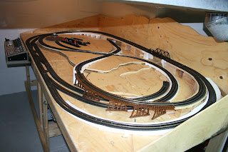
Just over a year later, my benchwork, track, electronics, and control system are finally complete! This weekend I made the last adjustments to my track-work, soldering a few more connections and leveling out a few last problem areas on the track. Both my Backmann EMD GP30 and my Kato SD-40 engines run perfectly on the layout and all aspects of the control panel and electronics, including the dual-cab wiring, work perfectly.
I also added a handle to the winch that raises and lowers the control panel, so I no longer have to use a screwdriver as a lever. I also came up with a latching system that will lock the control panel into place when it is in its raised position. This prevents all of the weight being on the winch cable, and also makes the control panel more rigid when in use.
To do this, I used two double ended bolts that I attached to the underside of my benchwork. I then drilled two holes through the control panel base so the protruding bolt end could pass through the control panel base when it was raised up against the benchwork. I then used butterfly bolts to support the control panel on these bolts. To make locking as easy as possible, I cut slots in the holes that I drilled, allowing the butterfly bolts to pass through the control panel base. This prevents the butterfly nuts from having to be completely undone. Once the butterfly bolt passes through the control panel base, it is turned 90 degrees, allowing the entire control panel to rest on the bolts (as seen above). Metal braces were added to prevent the bolts from damaging the hardboard.
I have now stated to plan the landscaping for me layout, which will be my project for the next couple months at least.
Abonneren op:
Reacties (Atom)


