donderdag 28 april 2011
Trackside Signals
My trackside signals are finally complete! When I purchased the little trackside signal face plates and matching LED lights off eBay for about $8.00 last year, I thought I was being really thrifty, which I was, however I then realized that I was now faced with the responsibility of having to make the light standards to hold these signals. Wiring was not an issue as I had incorporated these into my main wiring system, but I now had to find a way to make them look at least somewhat realistic on my layout.

As I mentioned before, the signals themselves were purchased off eBay for about $8.00. This included 10 black signal face plates which held 3 LED lights each, 30 LED lights (red, green, and yellow), and 30 matching resistors. Once the LED lights were glued into the face plates, I used telephone wire, which I soldered to the contact points on the LEDs. Telephone wire worked great as not only because it�s cheap and inexpensive, but the 4 wires are red, yellow, green, and black, which matched perfectly with the LED colours!


For paint, I used steel coloured enamel for all of the metal parts, such as the ladder and mast. I used a flat grey to simulate concrete on the base. The signal units themselves were painted flat black on all sides. Once the paint dried, I drilled holes through my benchwork, allowing the wires to run through to the underside, where I connected them to the rest of the wiring. I used temporary screws to hold them in place until I start my scenery.

The end result looked pretty good, considering I have never scratch built anything with styrene before. The cost was a lot less as well. Signals can run anywhere from $25 right up to $50 or $60 or higher for really nice ones. I spent in total about $30 for all 5 of mine. I know they aren�t exactly prototypical, but compared to some that I�ve seen in stores, I�m pretty satisfied with how they turned out.

For a diagram of how I wired my signals, click HERE, or visit my Wiring Diagrams page for other examples.
Read More..


To build the light standards, I went to my local hobby shop and visited the Evergreen Models styrene plastic display. Evergreen makes bulk styrene strips in almost every shape and size imaginable, which is great for these types of projects. I used 7/16� tubing for the mast, which is a little larger than most prototypical-sized masts, but this is the smallest size that would allow me to run the 8 wires through for the dual signals. I then cut notches in the tops of each mast to allow the signals to fit into them.


I then used slightly larger tubing that allowed the 3/16� tubing to fit snugly inside for the base support, as well as around the base of each signal to act as a support. The mast and support where then glued to a 1/16� base. I glued small rectangular pieces of thin styrene on the sides of each signal. This created a smooth transition from the signal to the mast. A second, smaller piece of styrene was then glued to that, simulating a maintenance door. I use poly-filler to fill in any gaps, and to smooth out any really rough edges.


The maintenance ladders were all hand made using .04" styrene strips. I carefully cut every rung to the exact size I needed, then carefully glued them to one of the side supports. I did this on a flat surface to ensure the rungs were all aligned with the support and were all level and square. Once dry, I glued on the other support. Once dry, I glued them directly to the signal units.


zondag 3 april 2011
One Year Mark
Just over a year later, my benchwork, track, electronics, and control system are finally complete! This weekend I made the last adjustments to my track-work, soldering a few more connections and leveling out a few last problem areas on the track. Both my Backmann EMD GP30 and my Kato SD-40 engines run perfectly on the layout and all aspects of the control panel and electronics, including the dual-cab wiring, work perfectly.


I also added a handle to the winch that raises and lowers the control panel, so I no longer have to use a screwdriver as a lever. I also came up with a latching system that will lock the control panel into place when it is in its raised position. This prevents all of the weight being on the winch cable, and also makes the control panel more rigid when in use.

To do this, I used two double ended bolts that I attached to the underside of my benchwork. I then drilled two holes through the control panel base so the protruding bolt end could pass through the control panel base when it was raised up against the benchwork. I then used butterfly bolts to support the control panel on these bolts. To make locking as easy as possible, I cut slots in the holes that I drilled, allowing the butterfly bolts to pass through the control panel base. This prevents the butterfly nuts from having to be completely undone. Once the butterfly bolt passes through the control panel base, it is turned 90 degrees, allowing the entire control panel to rest on the bolts (as seen above). Metal braces were added to prevent the bolts from damaging the hardboard.
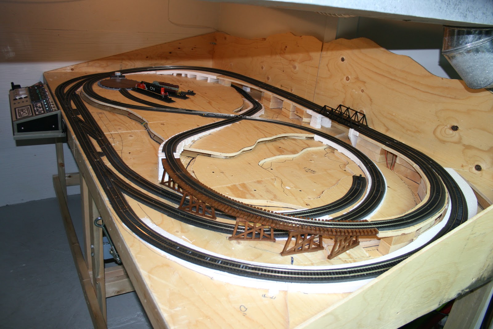
I have now stated to plan the landscaping for me layout, which will be my project for the next couple months at least.
zondag 27 maart 2011
Track Adjustments
It�s been a while since my last update, and even though I�ve been very busy with work, I�ve spent the last month and a half fine tuning my wiring and most of all, the track. I have not had much time to make any significant structural progress in the last little while, so I�ve spent the little time I�ve had to make adjustments to my track to ensure my engines run as smoothly as possible. As this is my first layout, every aspect of this project is a huge learning curve.
When I originally laid my track, I did not realize how extremely important it was to ensure track was perfectly level, especially through a curve or a curved grade. Even the smallest inconsistency in track level is enough to derail an engine. I found that these inconsistencies were most common where 2 pieces of track joined together. To solve this, I make sure each adjoining piece was perfectly level, then soldered them together to make sure they didn�t come apart afterwards. For areas where the actual road bed wasn�t level, I used thin foam risers under the track to keep the track perfectly level (as seen below).


I spent a lot of time running each of my engines back and forth over several section of problem track, closely watching each wheel to make sure it wasn�t lifting off the track. I managed to work out all the problem areas I was having, and everything runs a lot smoother. I also had to make a few small adjustments with my wiring, but nothing major.
I am now into the planning stages of building the actual ground terrain and elevations of my layout, which I hope to have completed by the end of May. I�m also trying to find the best way to build the standards for my trackside signals to mount to.
Read More..
When I originally laid my track, I did not realize how extremely important it was to ensure track was perfectly level, especially through a curve or a curved grade. Even the smallest inconsistency in track level is enough to derail an engine. I found that these inconsistencies were most common where 2 pieces of track joined together. To solve this, I make sure each adjoining piece was perfectly level, then soldered them together to make sure they didn�t come apart afterwards. For areas where the actual road bed wasn�t level, I used thin foam risers under the track to keep the track perfectly level (as seen below).


I am now into the planning stages of building the actual ground terrain and elevations of my layout, which I hope to have completed by the end of May. I�m also trying to find the best way to build the standards for my trackside signals to mount to.
maandag 24 januari 2011
Fixing the Grade
As this is my first layout, almost every aspect of the construction of model railroading is new to me. Most tasks are trial and error, and the amount I�m learning is extraordinary. At the same time, I�m also seeing where I went wrong, and the biggest error is the grade leading off of my trestle down to the 60 degree crossing. This has been a huge issue since I first designed the layout. Engines would high center at the top of the hill, and the cattle-guards would catch on the crossing, always causing derailment. This grade had to go, so back to the drawing board I went. With a little better planning, I managed to take the grade from almost 11%, down to just over 6%.

I removed the entire grade to start fresh. I took two things into account when re-planning the grade. The first was that I needed to try to make the distance from the 60 degree crossing to the end of the trestle longer. Second, I had to decrease the height of the trestle. These two items were essential in making a more successful grade.


To do this, I removed about 4 1/2 inches of the structure leading up to the trestle, thus allowing me to move the trestle over. Second, I had to lower one end of the trestle. I had almost � inch clearance above under-passing trains, so with a few modifications, I lowered the trestle about 1/2� on one end. The trestle now has a down grade of about 2%.

For the rest of the grade, I used a 4% foam starter grade from Woodland Scenics. This allowed me to easily transition from the crossing level up to the edge of the trestle. I then used custom cut foam supports to make sure the grade stayed in place and had proper support. I then added foam roadbed and once continuous piece of flex track to ensure a continuously smooth track. The end result was flawless! No more derailments and no more high centered engines!


A lesson about grades: I�ve done a bit of research about grades, and most prototypical modelers say nothing over 2%. For small layouts such as mine, this just isn�t possible, as I would prefer a slightly less prototypical railroad with lots of curves, elevation changes, bridges, mountains, etc. before I would a simple oval with no grades at all. However, with grades come great challenges, especially if it�s your first layout, such as mine. A few things I learned which might help you:
1. Plan first and know your limits! When designing your layout, try to give yourself as much room as possible for up/down grades. There are physical limits to how steep your train can travel.
2. Keep your grade as consistent as possible, with smooth transitions at each end. This is a problem I ran into. My transitions at the top and bottom of my downgrade were very extreme, resulting in my engine getting high centered at the top of the grade and bottoming out at the bottom of my grade.
3. Crossings require level track leading up to them to prevent couplers and cattle-guards from catching on the crossing track. If you have a grade leading to a crossing like I do, make sure the grade is no more than 2% for at least 8� before the crossing.
4. Experiment. Play around with different grades with actual track and engines before you make anything permanent. Allow for adjustments, and if it doesn�t work the first time, find what�s causing the issue and retry.
5. Don�t let anyone ruin your fun. Most professionals would laugh at a steep grade over 2%, but don�t let that discourage you. Make a layout as you see fit, after all, it�s your train and your imagination! Do what makes you happy and proud.
Read More..

I removed the entire grade to start fresh. I took two things into account when re-planning the grade. The first was that I needed to try to make the distance from the 60 degree crossing to the end of the trestle longer. Second, I had to decrease the height of the trestle. These two items were essential in making a more successful grade.


For the rest of the grade, I used a 4% foam starter grade from Woodland Scenics. This allowed me to easily transition from the crossing level up to the edge of the trestle. I then used custom cut foam supports to make sure the grade stayed in place and had proper support. I then added foam roadbed and once continuous piece of flex track to ensure a continuously smooth track. The end result was flawless! No more derailments and no more high centered engines!


1. Plan first and know your limits! When designing your layout, try to give yourself as much room as possible for up/down grades. There are physical limits to how steep your train can travel.
2. Keep your grade as consistent as possible, with smooth transitions at each end. This is a problem I ran into. My transitions at the top and bottom of my downgrade were very extreme, resulting in my engine getting high centered at the top of the grade and bottoming out at the bottom of my grade.
3. Crossings require level track leading up to them to prevent couplers and cattle-guards from catching on the crossing track. If you have a grade leading to a crossing like I do, make sure the grade is no more than 2% for at least 8� before the crossing.
4. Experiment. Play around with different grades with actual track and engines before you make anything permanent. Allow for adjustments, and if it doesn�t work the first time, find what�s causing the issue and retry.
5. Don�t let anyone ruin your fun. Most professionals would laugh at a steep grade over 2%, but don�t let that discourage you. Make a layout as you see fit, after all, it�s your train and your imagination! Do what makes you happy and proud.
Control Panel Winch System
With my electrical and control panel system complete, the last thing to do was to create a method to lower the control panel under my layout when not in use, and to raise it and keep it upright when needed. For this, I decided on a winch system. Simply turn the winch to raise the control panel into place, and reverse the winch to lower. The winch even holds the control panel up while in use.


Read More..

The system was quite easy to build. First, I purchased a mini-winch from a local hardware store, as well as a couple cable pulleys and other hardware to fasten it to my benchwork. For the cable, I used 1/16� aircraft cable covered in PVC and aluminum sleeves to create loops at each end. I planned a path for the cable to run, then drilled the necessary holes through my benchwork supports so the cable would come out centered right where I wanted it to lift the control panel to. I used 2 small pulleys to guide the cable to this point and to also ensure the cable was not contacting and of the benchwork.


I then used a fixed pulley bolted to the underside of my table top and ran the cable overtop, as seen below. This was then attached to a �U� bolt that was fastened to the control unit. The cable is rated for 95lbs safe working load, so it�s more than enough to lift and hold the unit.


woensdag 12 januari 2011
Holiday Wiring - Part II
My wiring and control panel are finally complete! The challenge over the last week and since my last post has been to move the control unit down to the basement and to hook it up to my layout.

I first attached the back of control unit base to the three 4x4� hinges with six �� bolts. This allows the control unit to fold under the table when not in use. However, for the moment I have not yet made a final decision on how the unit will latch when in its upright position, so for now I fastened it up with 3 screws.


I ran the leads from the control unit and hooked them up to the corresponding terminal screws on the previously installed terminal strips. The terminal strips made it very easy to detect any crossed over wires, and even easier to correct the problems as I only needed to swap the crossed wires to the correct screws. Remember, it doesn�t matter how organized or well planned your wiring layout is, mistakes will happen, so leave room to make corrections!


I kept the layout wires attached to the benchwork using small metal cable fasteners. These can be purchased at Canadian Tire for about $1.99 for 20, which compared to other products and retailers I found, is not a bad deal. Small zip-ties also help to keep wires organized and looking neat.


While testing my control unit, I realized that I needed a higher powered AC power source to power my switch machines, separate from my MRC Tech 4 280 power pack. For this, I mounted an older MRC power pack to the underside of my benchwork, and ran the new AC line back into my control box. This 2nd power source can also act as an additional 12VDC source in the future.


To provide reliable safe power to the different components, I installed a surge protected power bar below my benchwork for all the components to plug into. This is then connected by and extension cord to the wall outlet.


I didn�t plan a master on/off switch into my control panel design, which is something I most definitely should have done, as I have no way to turn my components off (not including the power pack). To solve this, I purchased a rocker switch ($2.99 from Princess Auto), rated at 120V 20A, which I tapped into the cord on the power bar. I then mounted the switch into a standard light switch cover panel that I painted dark brown. I drilled a hole into the front of my benchwork beside my control unit so the rocker switch panel could fit flush against the bench. This switch now cuts the power off to the power bar, so I can leave my layout plugged into the wall outlet at all times.


The track signals are still all displayed together on a temporary paper panel. This is purely for testing and making sure the signals work correctly when switching tracks. They will eventually be positioned on standards in the necessary positions along the tracks.


Other than a few small required adjustments, everything works great as far as the electrical system goes. The dual cab control works awesome, and I couldn�t be happier with how everything turned out. The next step will be to find a method to easily raise and lower the control panel and latch it when it�s upright. I�m also going to start smoothing out flaws in my track work and most importantly, take out the steep grade coming off of my trestle.


Also check out my Design and Planning page for updated schematics for different systems on my layout so far!
Read More..

I first attached the back of control unit base to the three 4x4� hinges with six �� bolts. This allows the control unit to fold under the table when not in use. However, for the moment I have not yet made a final decision on how the unit will latch when in its upright position, so for now I fastened it up with 3 screws.


I ran the leads from the control unit and hooked them up to the corresponding terminal screws on the previously installed terminal strips. The terminal strips made it very easy to detect any crossed over wires, and even easier to correct the problems as I only needed to swap the crossed wires to the correct screws. Remember, it doesn�t matter how organized or well planned your wiring layout is, mistakes will happen, so leave room to make corrections!


I kept the layout wires attached to the benchwork using small metal cable fasteners. These can be purchased at Canadian Tire for about $1.99 for 20, which compared to other products and retailers I found, is not a bad deal. Small zip-ties also help to keep wires organized and looking neat.


While testing my control unit, I realized that I needed a higher powered AC power source to power my switch machines, separate from my MRC Tech 4 280 power pack. For this, I mounted an older MRC power pack to the underside of my benchwork, and ran the new AC line back into my control box. This 2nd power source can also act as an additional 12VDC source in the future.


To provide reliable safe power to the different components, I installed a surge protected power bar below my benchwork for all the components to plug into. This is then connected by and extension cord to the wall outlet.


I didn�t plan a master on/off switch into my control panel design, which is something I most definitely should have done, as I have no way to turn my components off (not including the power pack). To solve this, I purchased a rocker switch ($2.99 from Princess Auto), rated at 120V 20A, which I tapped into the cord on the power bar. I then mounted the switch into a standard light switch cover panel that I painted dark brown. I drilled a hole into the front of my benchwork beside my control unit so the rocker switch panel could fit flush against the bench. This switch now cuts the power off to the power bar, so I can leave my layout plugged into the wall outlet at all times.


The track signals are still all displayed together on a temporary paper panel. This is purely for testing and making sure the signals work correctly when switching tracks. They will eventually be positioned on standards in the necessary positions along the tracks.


Other than a few small required adjustments, everything works great as far as the electrical system goes. The dual cab control works awesome, and I couldn�t be happier with how everything turned out. The next step will be to find a method to easily raise and lower the control panel and latch it when it�s upright. I�m also going to start smoothing out flaws in my track work and most importantly, take out the steep grade coming off of my trestle.


Also check out my Design and Planning page for updated schematics for different systems on my layout so far!
Abonneren op:
Posts (Atom)

